Tuesday, May 17, 2011
Parametric Constraints
This activity was done on inventor. In this activity we had to create this object on inventor according to certain measurements and directions given. To complete this task we had to use parametric equations instead of regular numerical measurements. This was a little challenging to work with the parametric equations instead of the actual numeric values. We had to calculate the missing values in order to figure out each dimension to use to create this on inventor.
Tuesday, April 12, 2011
Basic Assembly Constraints
For this activity we used many different shapes. We had to assemble these different shapes and put them together in a certain order, place, and position. To complete each of these steps and in order to put these different shapes into the base block we had to use the place constraints function. We had to use diferent methods to work the place constraints function. We used the mate contraint, flush contraint, and we changed themotion, etc. The basic purpose of this activity was for every student toknow how to use the place contraint function very well.
Friday, April 8, 2011
Reminder
All of these activities posted on the blog (exept for the ones sketched on paper) were all done on the 2011 version of Inventor.
Thursday, April 7, 2011
Water Bottle
In this activity I first inserted a water logo onto a sketch plane. Then I used the decal function to wrap the image around the pre-existing bottle design. After that all there was left to do was change the color of the bottle. (Decal is a function that allows the user to place an image onto a model surface)
Wrist Band
In this activity I used the emboss function to project a text down on the surface of the pre-existing wrist band and extruded the letters to a distance of 0.2 inches. The emboss function allows the user to raise a design from a surface or carve a design into a surface.
Left Half
In this activity I used the mirror function to add a duplicate mirror image of the existing geometry on the other side of the right face of the object. ( The mirror function allows the user to create a mirror image of the existing geometry)
Fillet Chamfers
In this activity I used the fillet function to apply a .25 inch radius to the corners of the original sketch. (The fillet function also can allow the user to create a rounded blend where two surfaces meet to form an angle). After I used the fillet function I used the chamfer function. With the chamfer function I applied a .25 inch by 40 degrees to the edges of the pre-existing sketch. ( The chamfer function also allows me to apply an angle surface where two existing surfaces meet to form an angle)
Threaded Rod
In this activity I used the the thread function to place right-hand 5/8 UNC thread along the entire length of the cylinder's curved face. The thread function also allows me to simulate the appearance of threads on curved surfaces either a cylinder or a hole.
Spring
In this activity I used the coil function to turn the pre-existing circle into a spring form by coiling around the y axis of the cartesian coordinate grid. The spring has a height of 6 inches and the circle is revolved around the y axis a total of 5 times. The coil function also allows the user to extrude a closed profile along a helical path around an existing axis.
Paper Clip
In this activity I used the sweep function to extrude the pre-existing circle along the existing path to create the form of a paper clip. I was able to do this because the sweep function allows me to extrude a closed profile along a path. The path may be opened or closed.
Rib Support
In this activity I used the rib function I turned the original existing line profile to create a .125 inch support web between the two perpendicular surfaces. A rib is a thin flat member that acts as a brace support. It's also referred to sometimes as a web.The rib function allows me to place a support between two intersecting surfaces.
Shell Tray
In this activity I used the shell function. This function will allow me to remove the unnecessary mass from a feature. The resulting geometry will have a wall thickness. I rotated the object so that it's underside was visible. Then I used the shell function to pocket out the material on the bottom side of the object.
Rectangular Pattern Along A Path
Just like in the previous activity I used the rectangular pattern function for this one. I used the function to copy the existing rectangular extrusions 13 times along the curved path of the base feature.
Rectangular Pattern
In this activity I used the rectangular pattern. This function allows the user to make copies of an existing feature in one direction or two directions together. I used the rectangular pattern function to copy the existing cylindrical extrusion six times horizontally and four times vertically.
Circular Pattern
In this activity I used the circular pattern. The pattern function allows the user to make multiple copies of an existing feature in one of three different ways. The circular pattern is also used to array a hole around a center axis. In this case I used the circular pattern to copy the existing hole on the circular plate a total of 10 times.
Loft
In this activity I used the loft function on a original sketch provided. The loft function allows the user to create a solid or surface by blending two or more shapes that are located on different planes. In this case i used the loft function to blend three different profiles into one solid object.
Drilled Holes
In this activity we used the hole function on the original sketch. With the hole function we drilled a counterbore, countersink, threaded hole, and clearance hole. I used different measurments and different taper degrees for each hole that was drilled.
Wednesday, April 6, 2011
Revolve
In this project we opened a file called. The revolve is a function that allows the user to extrude a closed profile around a fixed axis up to 360 degrees. We used that function in order to revolve the sketch around 360 degrees
Monday, March 28, 2011
Tapered Extrusions
In this activity we opened the file called Extrude-Taper, and extrude the square a distance of 1 inch with a taper angle of -10°.Extruded objects can be givenpositive or negative taper angle. A common example of a tapered extrusion is the design of an ice cube. The sides of the ice cube are tapered with a draft angle to allow the cube to be easily removed from the ice cube tray.
Intersect Extrusion
In this activity we opened a file called Intersect and performed an intersect extrusion on the sketch all the way through the existing object to observe what takes place. The intersect extrusion function will perform a Boolean addition and subtraction in one operation. Any part of the sketch profile that overlaps existing geometry will remain. The portion of the sketched profile and the existing geometry that do not overlap will be removed.
Mid-Plane Extrusion
For this activity we opened the mid-plane file and did a 1 inch midplane extrusion on the original sketch. The mid-plane function will join, cut, or intersect the selected sketch.
Friday, March 11, 2011
Thursday, March 3, 2011
Puzzle Cube Blueprint
Puzzle Cube
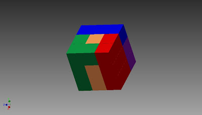
 This is the final puzzle cube. It was done on inventor. To create this cube I first had done the smaller shapes on inventor. Five shapes were created, and all the five shapes had 27 cubes in total. Once I completed the shapes I assembled them. That meant that I was able to put them together to create this final cube.
Animated Puzzle Cube
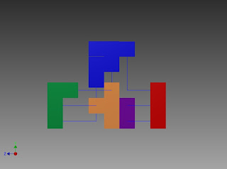
 These shapes are the combinations I have done in order to create my puzzle cube. However, this is already an assembly of all the shapes together. After I used inventor to create these simple shapes i did an assembly. An assembly cause the shapes to go together. This will help create the final puzzle cube in the end.
Tuesday, February 8, 2011
Welcome !
Hi! My name is Kathleen Silva and I will be using this blog as a portfolio for my Engineering Design class. I will be posting my projects and examples along with a brief description of what I did. Please check back to see my work! |
Subscribe to:
Comments (Atom)


